Centrifugation Theory
What is centrifugation ?
Centrifugation is a technique used for the separation of particles from a solution according to their size, shape, density, viscosity of the medium and rotor speed.
The particles are suspended in a liquid medium and placed in a centrifuge tube. The tube is then placed in a rotor and spun at a define speed.
Separation through sedimentation could be done naturally with the earth gravity, nevertheless, it would take ages. Centrifugation is making that natural process much faster.
Rotation of the rotor about a central axis generates a centrifugal force upon the particles in the suspension.
Which factors have an influence on centrifugation :
- Density of both samples and solution
- Temperature/viscosity
- Distance of particles displacement
- Rotation speed
A centrifuge is a device that separates particles from a solution through use of a rotor. In biology, the particles are usually cells, subcellular organelles, or large molecules, all of which are referred to here as particles.
There are two types of centrifuge procedures; one is preparative, the purpose of which is to isolate specific particles, and the other is analytical, which involves measuring physical properties of the sedimenting particles.
As a rotor spins in a centrifuge, a centrifugal force is applied to each particle in the sample; the particle will then sediment at the rate that is proportional to the centrifugal force applied to it. The viscosity of the sample solution and the physical properties of the particles also affect the sedimentation rate of each particle.
At a fixed centrifugal force and liquid viscosity, the sedimentation rate of a particle is proportional to its size (molecular weight) and to the difference between the particle density and the density of the solution.

In a solution, particles whose density is higher than that of the solvent sink (sediment), and particles that are lighter than it float to the top.
The greater the difference in density, the faster they move. If there is no difference in density (isopyknic conditions), the particles stay steady.

To take advantage of even tiny differences in density to separate various particles in a solution, gravity can be replaced with the much more powerful “centrifugal force” provided by a centrifuge.

Two forces counteract the centrifugal force acting on the suspended particles:
- Buoyant force: force with which the particles must displace the liquid media into which they sediment.
- Frictional force: force generated by the particles as they migrate through the solution.
Particles move away from the axis of rotation in a centrifugal field only when the centrifugal force exceeds the counteracting buoyant and frictional forces resulting in sedimentation of the particles at a constant rate.

Relative Centrifuge Force (RCF) expressed in xg (multiple of earth gravitational force)
RFC = 1,118 x R x (rpm /1000)²
R is radius in cm
rpm : Speed in Revolutions per minute
- As a result, for the same speed, a radius 20% bigger gives a number of xg 20% higher.
How to convert between times gravity (×g) and centrifuge rotor speed (RPM)?
Certain procedures necessitate precise centrifugation conditions, which must be specified in terms of relative centrifugal force (RCF) expressed in units of gravity (times gravity or × g). Many microcentrifuges only have settings for speed (revolutions per minute, RPM), not relative centrifugal force. Consequently, a formula for conversion is required to ensure that the appropriate setting is used in an experiment. The relationship between RPM and RCF is as follows:
g = (1.118 × 10⁻⁵) x R x S²
Where g is the relative centrifugal force, R is the radius of the rotor in centimeters, and S is the speed of the centrifuge in revolutions per minute. Values of RCF in units of times gravity (× g) for common microcentrifuge rotor radii appear in the following conversion table. As an example, centrifugation of a sample at 5,000 RPM in a microcentrifuge that has a rotor with a radius of 7 cm will deliver a centrifugal force of 1,957 × g.
Centrifugation speed and time often are not critical factors in routine sample-handling procedures involving a benchtop microcentrifuge. Usually, as long as speed and time are sufficient to ensure that cells, debris or resin are pelleted effectively, it does not matter if the speed is faster or the time longer than necessary. For this reason, many protocols do not specify a particular centrifugal force to be applied but instead indicate some general guideline such as “centrifuge at high speed for 1 minute.”
Example of Conversion Table
| Speed (RPM) | Rotor Radius (from center of rotor to sample) in centimeters | ||||||||||||||
| 4500 | 906 | 1132 | 1358 | 1585 | 1811 | 2038 | 2264 | 2490 | 2717 | 2943 | 3170 | 3396 | |||
| 5000 | 1118 | 1398 | 1677 | 1957 | 2236 | 2516 | 2795 | 3075 | 3354 | 3634 | 3913 | 4193 | |||
| 5500 | 1353 | 1691 | 2029 | 2367 | 2706 | 3044 | 3382 | 3720 | 4058 | 4397 | 4735 | 5073 | |||
| 6000 | 1610 | 2012 | 2415 | 2817 | 3220 | 3622 | 4025 | 4427 | 4830 | 5232 | 5635 | 6037 | |||
| 6500 | 1889 | 2362 | 2834 | 3306 | 3779 | 4251 | 4724 | 5196 | 5668 | 6141 | 6613 | 7085 | |||
| 7000 | 2191 | 2739 | 3287 | 3835 | 4383 | 4930 | 5478 | 6026 | 6574 | 7122 | 7669 | 8217 | |||
| 7500 | 2516 | 3144 | 3773 | 4402 | 5031 | 5660 | 6289 | 6918 | 7547 | 8175 | 8804 | 9433 | |||
| 8000 | 2862 | 3578 | 4293 | 5009 | 5724 | 6440 | 7155 | 7871 | 8586 | 9302 | 10017 | 10733 | |||
| 8500 | 3231 | 4039 | 4847 | 5654 | 6462 | 7270 | 8078 | 8885 | 9693 | 10501 | 11309 | 12116 | |||
| 9000 | 3622 | 4528 | 5433 | 6339 | 7245 | 8150 | 9056 | 9961 | 10867 | 11773 | 12678 | 13584 | |||
| 9500 | 4036 | 5045 | 6054 | 7063 | 8072 | 9081 | 10090 | 11099 | 12108 | 13117 | 14126 | 15135 | |||
| 10000 | 4472 | 5590 | 6708 | 7826 | 8944 | 10062 | 11180 | 12298 | 13416 | 14534 | 15652 | 16770 | |||
Need more? Try our online converter!
Separations are a critical step in your workflow; thus it’s important to consider the centrifuge requirements and technical specifications for your applications, from selecting the appropriate speed and g-force to exploring the latest trends in centrifugation.
Microcentrifuges
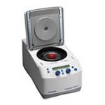


Compact, safe and easy-to-use microcentrifuges combine power with versatility and convenience. Those microcentrifuges can support all your micro volume protocols—including nucleic acid minipreps, spin columns, PCR tubes and strips, and hematocrit capillaries—in a small footprint.
Small Benchtop Centrifuges
Mainly used for mall amount of material that rapidly sediment like yeast cells, erythrocytes etc., they offer maximized capacity in a compact footprint, accomodating multi-laboratory settings with the flexibility to adapt to your evolving clinical and research needs:
- Research Applications: Cellular Biology, Microbiology, Genomics / Molecular Biology, Proteomics, Biochemistry, Pharmaceutical Studies.
- Clinical Applications: Clinical Chemistry, Clinical Microbiology, Hematology, Immunology, Clinical Studies.
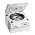

General Purpose Centrifuges
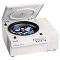
Those centrifuges feature innovative rotor technologies designed for improved benchtop performance and flexibility, greater sample capacity, and increased speed.
There is lots of choice of rotors, buckets and adaptators to fit your needs.
Large Capacity Centrifuges
Designed to combine dependable performance and ease‐of‐use with advanced functionality, our large capacity centrifuges provide reproducible separations for high‐throughput applications such as blood banking and bioprocessing.
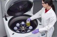
Superspeed Centrifuges
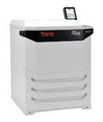
Combine cutting-edge technology, high-speed performance, and versatile rotor capacities, allowing you to maximize productivity with impressive acceleration rates.
This will allow you to collect micro-organism, cellular debris, larger cellular organelles and precipitated proteins.
Ultracentrifuges
Combining outstanding speed, safety and ergonomics in a compact design, ultracentrifuges and micro-ultracentrifuges are designed to deliver exceptional speed.
It is employed for separation of macromolecules/ligand binding kinetic studies, separation of various lipoprotein fractions from plasma and deprotonisation of physiological fluids for amino acid ananlysis.

Centrifuge rotors fall into three categories: swinging-bucket rotors, fixed angle rotors, and vertical rotors. Each category is designed to address three key factors:
1) type of centrifugation (differential, rate-zonal, or isopycnic),
2) speed,
3) volume range.
Of these categories, fixed-angle and swinging-bucket rotors are the most common styles for benchtop, lowspeed, and high-speed floor-model centrifuge applications. Vertical rotors are used primarily in ultracentrifugation.
Swinging bucket rotors

Swinging-bucket rotors are ideal for separating large-volume samples (up to 12 L) at low speeds.
A swinging-bucket rotor system consists of three parts:
1) The rotor body attaches to the centrifuge drive and has four or six arms to support the buckets,
2) the buckets are placed onto the arms of the rotor body,
3) trunnion pins are used to hold the buckets in place.
Additional accessories can be added as needed to tailor the rotor for a specific application or sample format. For example, large-volume rotors frequently offer a wide variety of adapters (plastic inserts) that can be placed into the buckets to hold the desired tube size. Certain buckets offer sealing lids, which provide biocontainment for potentially hazardous samples.
This type of centrifuge allow the tubes placed in the cups of the rotor to assume a horizontal plane when the rotor is in motion and a vertical position when it is at rest. During centrifugation particles travel uniformly and constantly along the tube while the tube is at right angle to the shaft of centrifuge; thus the sediment is distributed uniformly against the bottom of the tube and remains there when rotor stops, with liquid above it. This liquid can be decanted off and both liquid and sediment can be separated for analysis. The spinning rotor offers considerable resistance to rotation and generates heat due to air friction.
Fixed angle rotors

Fixed-angle rotors are the most ubiquitous rotors used in centrifugation.
The majority are used for basic pelleting applications (differential separations), either to pellet particles from a suspension and discard the excess debris, or to collect the pellet.
The cavities in these rotors range in volume from 0.2 mL to 1 L, with speeds ranging from single digits to 1,000,000 × g (relative centrifugal force, RCF).
Two factors determine the type of fixed-angle rotor required:
1) Desired g-force (RCF),
2) desired volume.
Generally speaking, the size of the rotor is inversely proportional to its maximum speed capability (i.e., the larger the rotor, the lower the maximum speed). An important specification when selecting a fixed-angle rotor is the K factor, which indicates the pelleting efficiency of the rotor at top speed, taking into account the maximum and minimum radius (pathlength) of the rotor cavity. A low K factor indicates a higher pelleting efficiency; therefore, the K factor can be a useful metric for comparing the speed at which particles will pellet across a range of rotors.
Here tubes are held in a fixed position at angles from 250 to 400 to the vertical axis of rotation. Upon centrifugation particles are driven outward horizontally but strike the side of the tube so that the sediment packs against the side and bottom of the tube with the surface of sediment parallel to the shaft of the centrifuge. As rotor slows down or stops, gravity causes the sediment to slide down the tube, usually a poorly packed pellet is formed.
Vertical tube rotors

They are considered as zero angle fixed angle rotors in which the tubes are aligned vertically in the body of the rotors at all times.
Vertical rotors are fairly specialized — their most common use is during ultracentrifugation for isopycnic separations, specifically for the banding of DNA in cesium chloride. In this type of separation, the density range of the solution contains the same density as the particle of interest; thus the particles will orient within this portion of the gradient. Isopycnic separations are not dependent on the pathlength of the gradient but rather on run time, which must be sufficient for the particles to orient at the proper position within the gradient.
Vertical rotors have very low K factors (typically in the range of 5–25), indicating that the particle must only travel a short distance to pellet (or in this case form a band); therefore run time is minimized. Once it is determined that a vertical rotor is appropriate for the end-user application, volume and speed become the deciding factors for which rotor to use.


.jpg-150.jpg)


